Converting an
HP Z3801A GPS RX to RS-232C I/O

by Dave Fifield, AD6A

If you prefer to read this article in Italian, I6YPK has kindly translated it - you can see it HERE. If anyone else has translated it into any other language, please let me know and I'll add a link to it here.

A lot of these units are still making their way onto the surplus market as they are stripped out of cellular phone base station sites around the country (USA). At first glance, many people would question their usefulness/worth, since they don't have a built-in display or any means of control other than an external RS-422 port. In fact, nothing could be further from the truth. The HP Z3801A units make marvelous GPS locked high stability 10MHz sources with an accuracy of 1 part in a billion (1 in 10E9) that you can use to lock your test equipment to or use as a very stable source to phase lock the local oscillator of any microwave transverter to.

They are easy to set up and control using free software. There are schematics for RS-422 to RS-232 converters on the web as well as ready-built converters you can buy. It is not necessary to do this however, as the Z3801A can easily be converted to RS-232 control that will interface directly to any PC serial COM port. All the RS-232 electronics is already inside the unit! All you have to do is enable it with some simple links.

While surfing the web for information on the unit, I saw that another ham, WB6MOB, had found that he was able to convert these units to RS-232. However, the information provided was limited and so I thought it would be nice to put up a webpage with more detail. What follows is a description of how I converted my two units and connected them up to my PC. YMMV. If you have any questions, please email me:


1. Using a T10 Torx driver, remove the 10 screws from the top of the box:


2. Remove the lid. Then, disconnect the main power connector on the PSU PCB:

3. Using a T10 Torx driver, remove the 6 screws holding the PSU board in place:

4. Carefully flip the PSU board up and over, out of the way:

5. Using a 3/16" nut driver, remove the 2 screws from the 25-pin D connector J3 on the rear panel:

6. Disconnect the 10MHz output coax connector from J17 on the main PCB:


7. Disconnect the GPS RX input coax connector from the GPS RX sub-assembly on the main PCB:


8. Using a T15 Torx driver, remove the 6 screws holding the main PCB in place:


9. Carefully maneuver the main PCB out of the case. You may notice some sticky grey gunge on the chassis like this:


10. This stuff is what's left of 2 melted/chemically altered plastic stick-on feet that were stuck onto the chassis to prevent too much flexing of the main PCB. It may be on the underside of the main PCB too, like this:


11. This messy stuff cleans up easily with alcohol (I used rubbing alcohol from Safeway, $0.99):


12. Locate the corner of the main PCB that has the 25-pin D connector J3 in it. Notice that there are three rows of eight 0.1" spaced PCB holes labeled "RS232" and "RS422":


13. Carefully flip the main PCB over and locate the 5 zero Ohm resistors as circled below - they are right next to the 3 x 8 rows of holes identified in step 12 above - you have to remove these resistors (very carefully, of course!):


14. I used two soldering irons to remove the 5 zero Ohm resistors. This technique works very well indeed and virtually guarantees that you will get the parts off fast without any damage to the PCB. Note that I actually did this step before I cleaned up the grey gunge!


15. Next, flip the PCB back over and solder in three rows of eight standard 0.1" spacing headers:


16. Place 8 shorting links onto the RS232 links, like so:


17. That's it, you are done. Well, not quite, you still have to re-assemble the unit in the reverse order you took it apart:


18. Once you have the unit all back together, you need to make an RS-232C cable to connect it to a COM port. Most people have 9-pin D COM ports on their desktop/laptop PC's these days, so this is what I will describe:

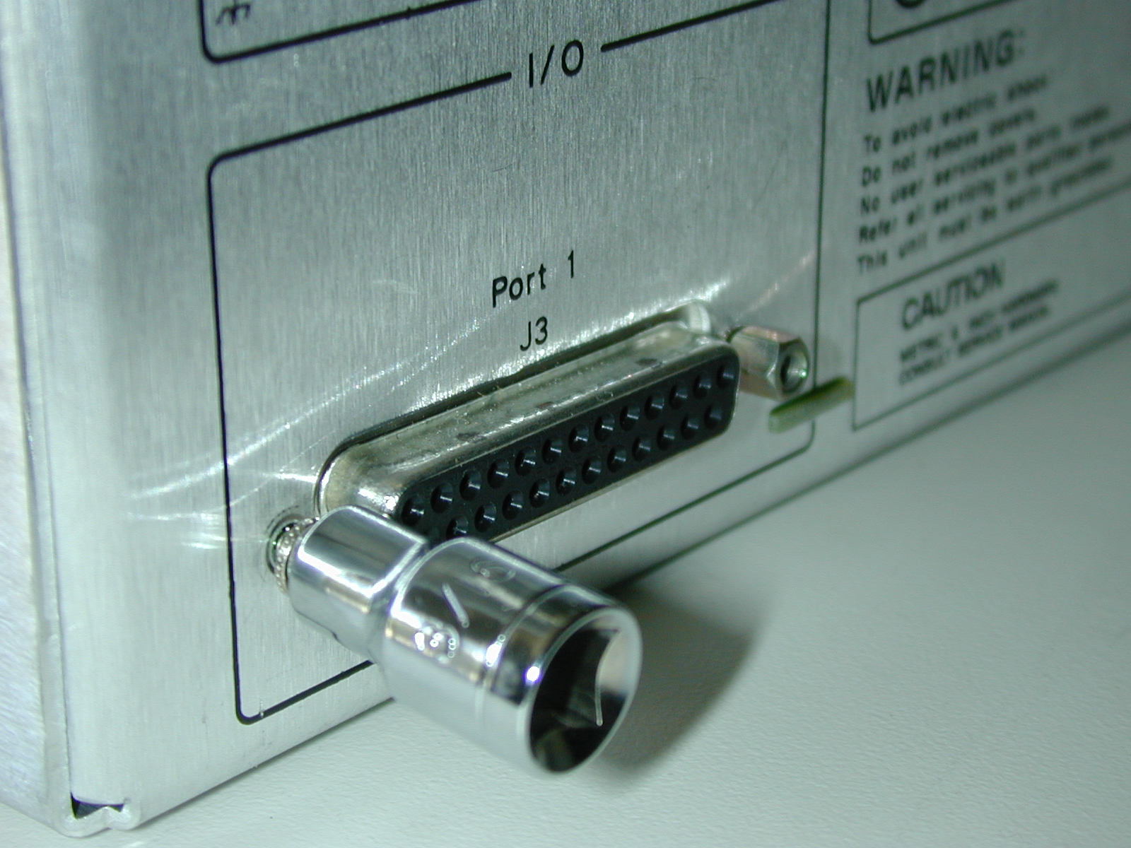
9-pin D female (PC's COM port) to 25-pin D male (Z3801A port cable) wired as follows:

        TXD (pin 3, 9-pin) to RXD (pin 3, 25-pin)

        RXD (pin 2, 9-pin) to TXD (pin 2, 25-pin)

        GND (pin 5, 9-pin) to GND (pin 7, 25-pin)

These are the only 3 RS-232 connections you need. Since there are 1PPS and 10MHz clock outputs on several other pins of the 25-pin D (J3), I recommend that you only wire up these three pins initially (that is, don't use a full 25-way cable out of J3, make your own with just these three wires connected).

19. You are now all set to try it out. I recommend you use the SatStat software to talk to the unit. It is specially written for this purpose and will save you loads of time messing around learning the command set. This software, plus lots more advice about power supplies etc. is available from K8CU's website here.

20. When you run the software, you will first need to configure the COM port. Note that the software only seems to know about COM1 - COM4, a minor drawback IMO. Configure the COM port as follows:

Baud Rate = 19200

Data Bits = 7

Stop Bits = 1

Parity = Odd

COM Port = {1|2|3|4}

Flow Control = None

Once you have this entered and the Z3801A powered up with an antenna, click on "CommPort - Port Open" and the software (which I can send you if you email me) should immediately begin talking to your Z3801A, showing the system status. If this is the first time you have used the unit, I recommend you simply send the survey command to start things off on the right foot. To do this, click on the "Control & Query" window, then select the Control menu and then choose the "Survey" command and send it. Make sure the Z3801A accepts the command and then walk away and leave it on for an hour or two. When you come back, the survey should have completed and you should be in "Hold" mode with the correct GPS position. Leave the unit on for another 24 hours so that it fine tunes everything nicely.

That's it. Enjoy. I'm going to use one of mine in my lab as an accurate 10MHz source and the other in a box with batteries as my 10MHz source for microwave portable operations. The 10MHz source will go into "Holdover" mode with no antenna connected. The oscillator will remain plenty stable enough for a day's hilltopping/roving without having a GPS antenna connected.

73, Dave, AD6A